11 - Operation and use of the router
Generality
The Photovoltaic Router is in charge of analyzing the direction of the current at the level of the electric meter thanks to the probe placed on the Phase wire.
If the current is positive, the house consumes current from the electrical network.
If the current is negative, the solar panels present provide more energy than what the house currently consumes.
The purpose of the Pv router is therefore to increase the power of a remote load to compensate for this overproduction.
In general, this load is an energy or heat storage area that will be needed at a later time (Hot water, mass heating, battery, EV, etc.)
The self-consumption of your photovoltaic installation is therefore maximized, and its impact on the electrical network is reduced. (and associated costs)
Detail of the Web part.
Once the code has been uploaded (firmware and filesystem) and the entire router has been installed, it is possible to connect with your Web browser to the IP that is displayed on your PV router display.
You can therefore consult the information sent by the PV router.
On this interface you will find a gauge with the power requested from the network and the power requested from the dimmers (in %)
For the power requested from the network, there are 3 states that can be configured:
- Stable: the PV router has stabilized consumption.
- Injection: The Pv router will gradually increase the load to stabilize consumption
- Grid: The Pv router will reduce the load to limit the needs of the house.
On this interface, there is also an ON/OFF Oled button which is in charge of turning the Oled screen on or off.
it can just be a delay on or off until the next button press.
(ON/OFF or timer)
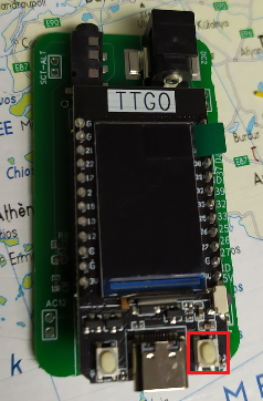
This button is also remote on the PV router, it is the right button of the TTGO
Configuring the web part.
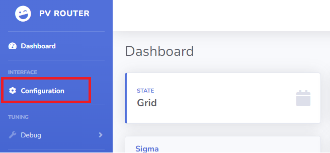
on the base page, there is a "configuration" link that points to the /setup.html page
this page allows you to configure all the functions of the router.
MQTT: (Optional)
MQTT Server: IP of the MQTT server which collects information from the router (mainly for logs)
MQTT Publish: Indicates the location of the publication (Jeedom and Domoticz compatible data)
IDX POWER and IDX DIMMER: are the IDs configured on your home automation servers.
DIMMER:
Dimmer IP: Is the IP of your 1st Dimmer which will receive the command from the PV router
Consumption Limit (Delta): Is the value of the power from which the PV router will reduce the power of the dimmer
Injection limit (deltaneg): Is the value of the power from which the PV router will increase the load of the dimmer
Connected load/W: Is the estimated power connected to the 1st dimmer, this value in W facilitates regulation.
Limiter in %: Is the 1st security to avoid asking too much power from your dimmers.
the value is defined by the sum of all the dimmers that are associated with your PV router
For example where your 1st router is limited to 80% power and the 2nd is limited to 40%.
the sum of the 2: "120" is therefore entered in the Limiter box.
Functional configuration
If the SCT013 probe is connected upside down and therefore sends a negative value instead of positive, the "polarity" button must be unchecked
The COSPHI represents the offset between the sync carrier and the network, this value is by default at 5
It is not advisable to touch it.
To preserve the life of the display, it can be switched on on demand
Special feature of AP mode (access point)
By default, if the wifi file is not configured, the router goes into AP mode, it will create its own wifi network.
the Wifi network will be of the PV-ROUTER-XXXX type.
The password will be PV-ROUTER
the IP address of the PV router will be 192.168.4.1
if a dimmer has been configured to connect to this network, the PV router will automatically detect it, and route the photovoltaic surplus to this dimmer.
For reasons of use, it is currently only possible to put 1 single dimmer on the network in AP mode.


No Comments