# Photovoltaic router and numeric dimmer
# Photovoltaic router
# 01 - Install of Visual Studio Code
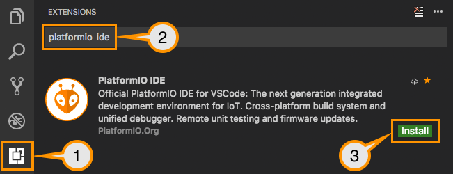
To transfer the code to the microcontroller (ESP32 or TTGO) it is necessary to install[ Visual Studio Code](https://code.visualstudio.com/).
Once installed, you must install the [PlatformIO](https://platformio.org/install/ide?install=vscode) package which will be used later for all your projects and not only for the Dimmer or the Pv router.
# 02 - Copy or update repository sources
The sources are available on the Github (a code repository web server)
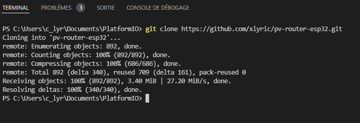
once your Visual Studio is launched, go to your Terminal and type
```shell
git clone https://github.com/xlyric/pv-router-esp32.git
```
it will then clone the repository on your machine and you can adapt the code to your needs and upload it.
[](https://pvrouteur.apper-solaire.org/uploads/images/gallery/2022-03/image-1648136080114.png)
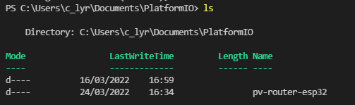
you can then go to the directory created during the command
[](https://pvrouteur.apper-solaire.org/uploads/images/gallery/2022-03/image-1648136251752.png)
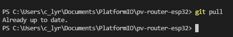
In the case of an update, you can update your code again with the following command
```shell
git pull
```
[](https://pvrouteur.apper-solaire.org/uploads/images/gallery/2022-03/image-1648136329142.png)
#### Default configuration
If you want to keep the router in access point mode, you don't have to do anything, just upload the code.
If you want to use it on your wifi network, you have to configure 1 file to operate the Router
In the Data directory which contains the HTML pages, you must rename the file wifi.json.ori
in wifi.json and enter the connection parameters of your internet box
# 03 - USB code upload
Uploading is done with Visual Studio Code (VS) using the PlatformIO tab
[](https://pvrouteur.apper-solaire.org/uploads/images/gallery/2022-03/image-1648136519736.png)
During your 1st Upload, you must connect your TTGO or ESP32 to your PC with a USB cable
Thanks to VS you will load in the microcontroller the firmware and the HTML pages of the router
There are 2 uploads to do:
- one for the firmware (the system code)
- one for the filesystem (configuration files and website)
Then you can directly upload the code remotely with the /update page of the router
# 04 - Remote code upload
Uploading is done with Visual Studio Code (VS) using the PlatformIO tab
[](https://pvrouteur.apper-solaire.org/uploads/images/gallery/2022-03/image-1648136519736.png)
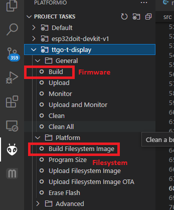
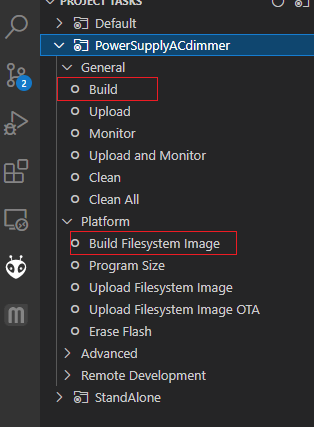
your code being already present on the router, you can now directly generate the binary files to be sent.
In general, only the General Build is to be done.
The Build Filesystem Image is only there to update the HTML pages when functionalities evolve.
[](https://pvrouteur.apper-solaire.org/uploads/images/gallery/2022-03/image-1648136931479.png)
once the build is done:
[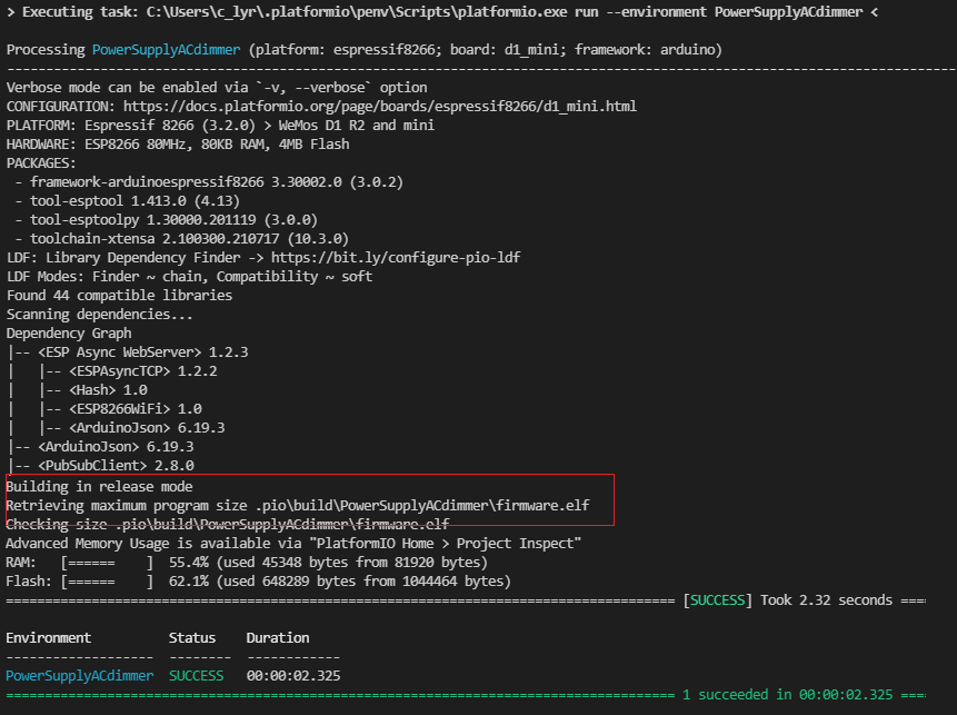](https://pvrouteur.apper-solaire.org/uploads/images/gallery/2022-03/image-1648137170040.png)
it shows where the firmware is.
all you have to do is connect with the internet browser on your pv router and go to the /update page
[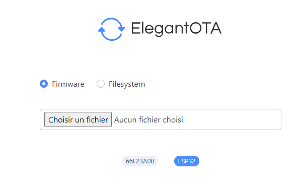](https://pvrouteur.apper-solaire.org/uploads/images/gallery/2022-03/image-1648137301517.png)
and upload the firmware
#### Case of a Filesystem update
In the case of updating the Filesystem ( HTML file ), it's the same procedure, you just have to take the Filesystem binary and select Filesystem.
Warning: before uploading it is important to check that the data/wifi.json file is present on your repository and contains the connection information to your internet box.
it is also preferable before the update to save its configuration by going to the /config.json web page and copy/paste the information into the config.json of your repository (or save it in a third-party file)
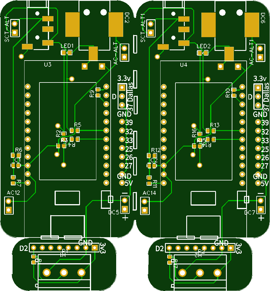
# 10 - Creation of the PV router with a TTGO-Tdisplay
The creation of the Pv router with the card adapted for the TTGO Tdisplay is currently the fastest
[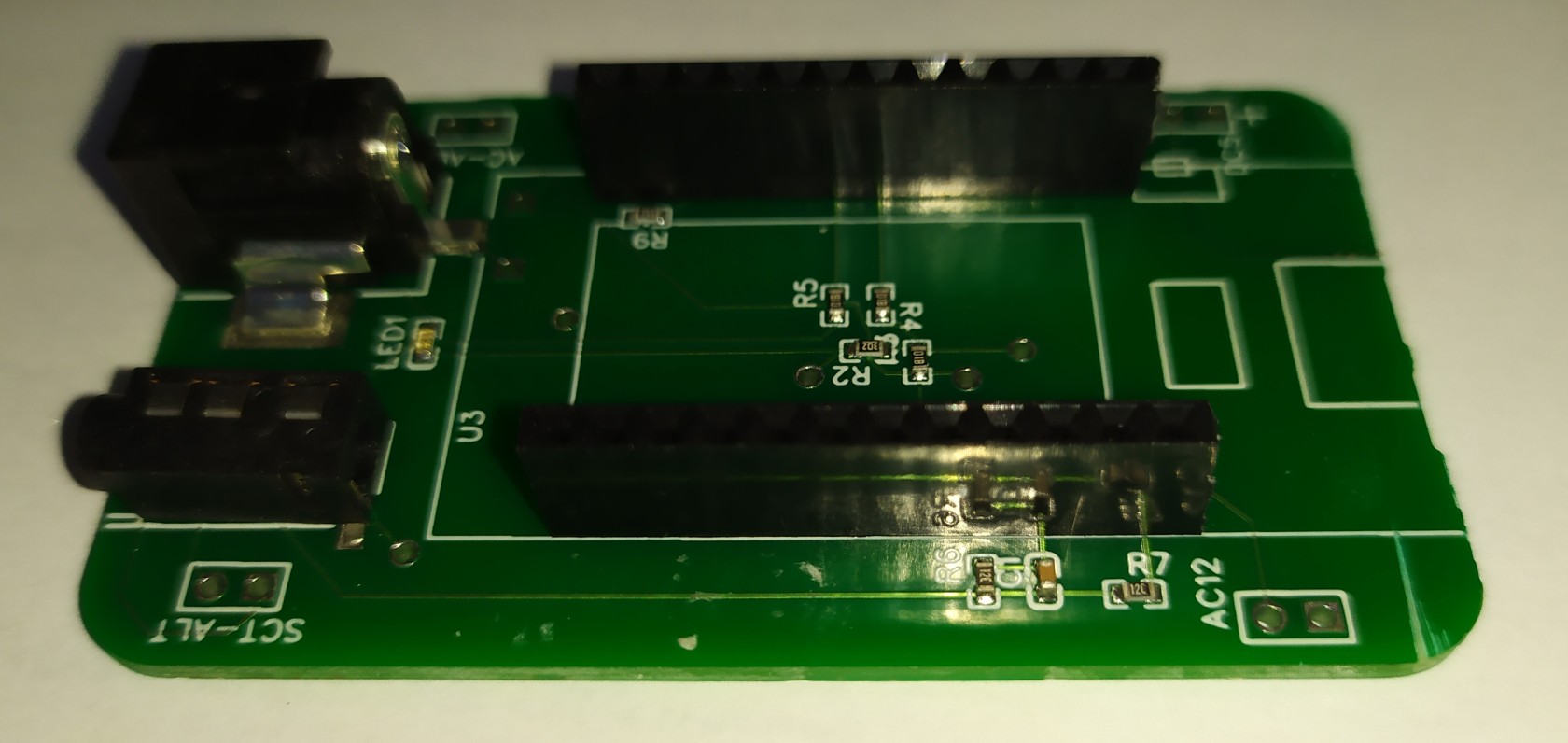](https://pvrouteur.apper-solaire.org/uploads/images/gallery/2022-03/image-1648140294690.jpg)
this card can be ordered from the [APPER association](https://www.helloasso.com/associations/apper/formulaires/4), and its purchase is considered a donation and therefore partially tax deductible.
The rest of the components can be ordered from various component suppliers. ([Aliexpress](https://fr.aliexpress.com/item/33048962331.html), [Amazon](https://amzn.to/3wyeFcy)...)
The display: TTGO Tdisplay
[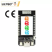](https://pvrouteur.apper-solaire.org/uploads/images/gallery/2022-03/image-1648139842187.png)
[Amazon](https://amzn.to/3wyeFcy)...
**the probe SCT013-30A**
[Amazon](https://amzn.to/3CtCHqi)
[](https://pvrouteur.apper-solaire.org/uploads/images/gallery/2022-03/image-1648139910136.png)
**A 12V recovery power supply**
\- You have to find an old 9-12V coil power supply in a drawer to convert it to AC power
(or buy a power supply from [openenergymonitor.com](https://shop.openenergymonitor.com/ac-ac-power-supply-adapter-ac-voltage-sensor-euro-plug/))
[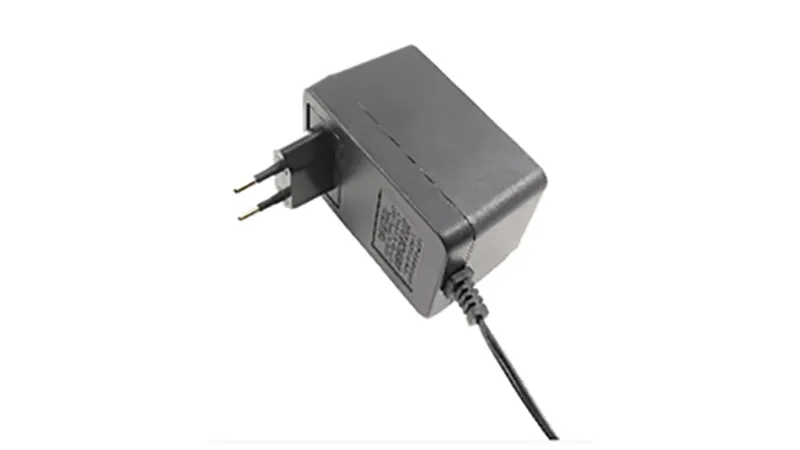](https://pvrouteur.apper-solaire.org/uploads/images/gallery/2022-03/image-1648140231834.png)
12V AC power supplies as standard are very rare.
A classic USB power supply (1A max)
[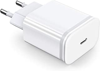](https://pvrouteur.apper-solaire.org/uploads/images/gallery/2022-03/image-1648140103860.png)
The card once mounted with the TTGO can be integrated into the box sold by the TTGO
[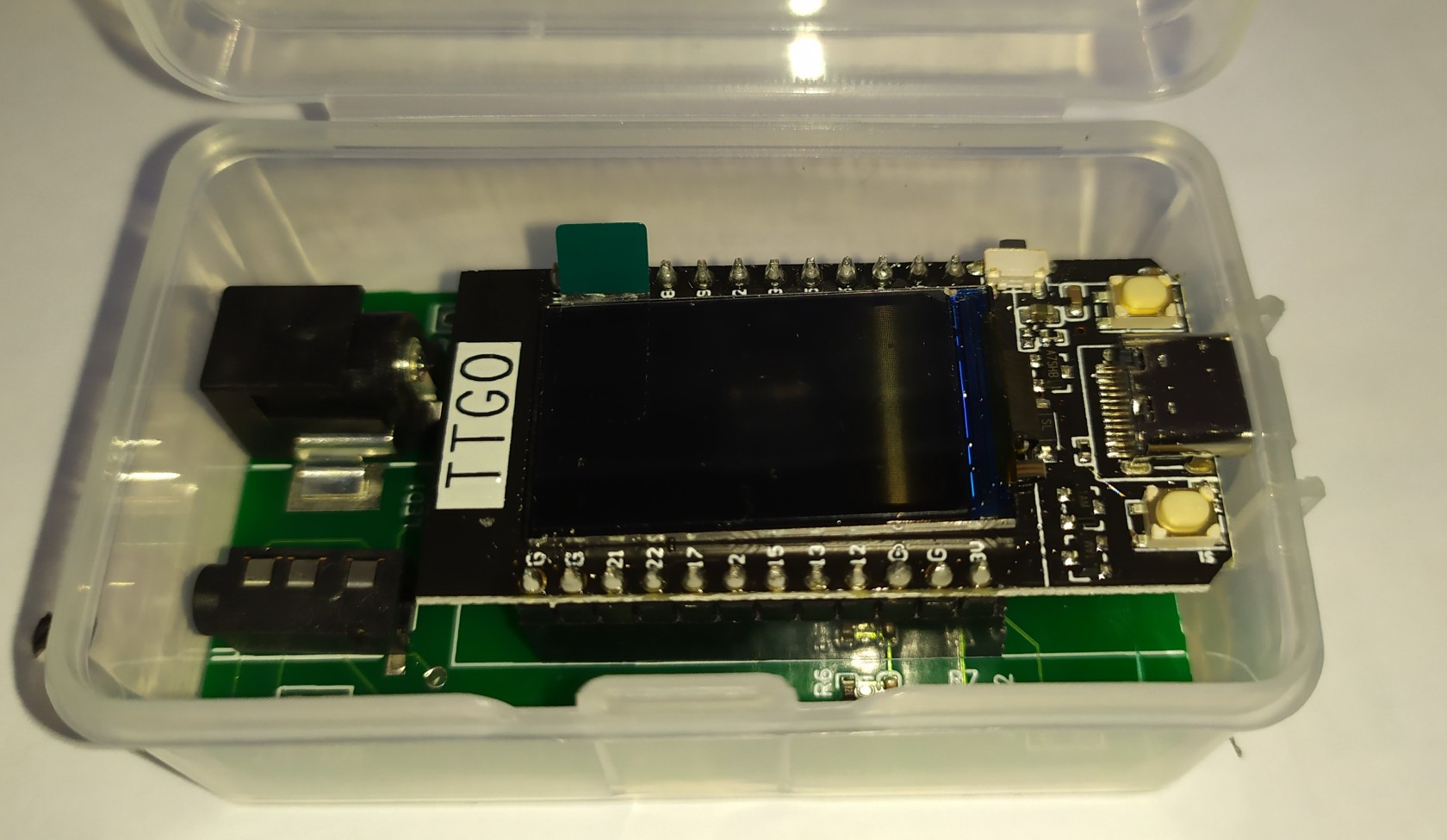](https://pvrouteur.apper-solaire.org/uploads/images/gallery/2022-03/image-1648140379598.jpg)
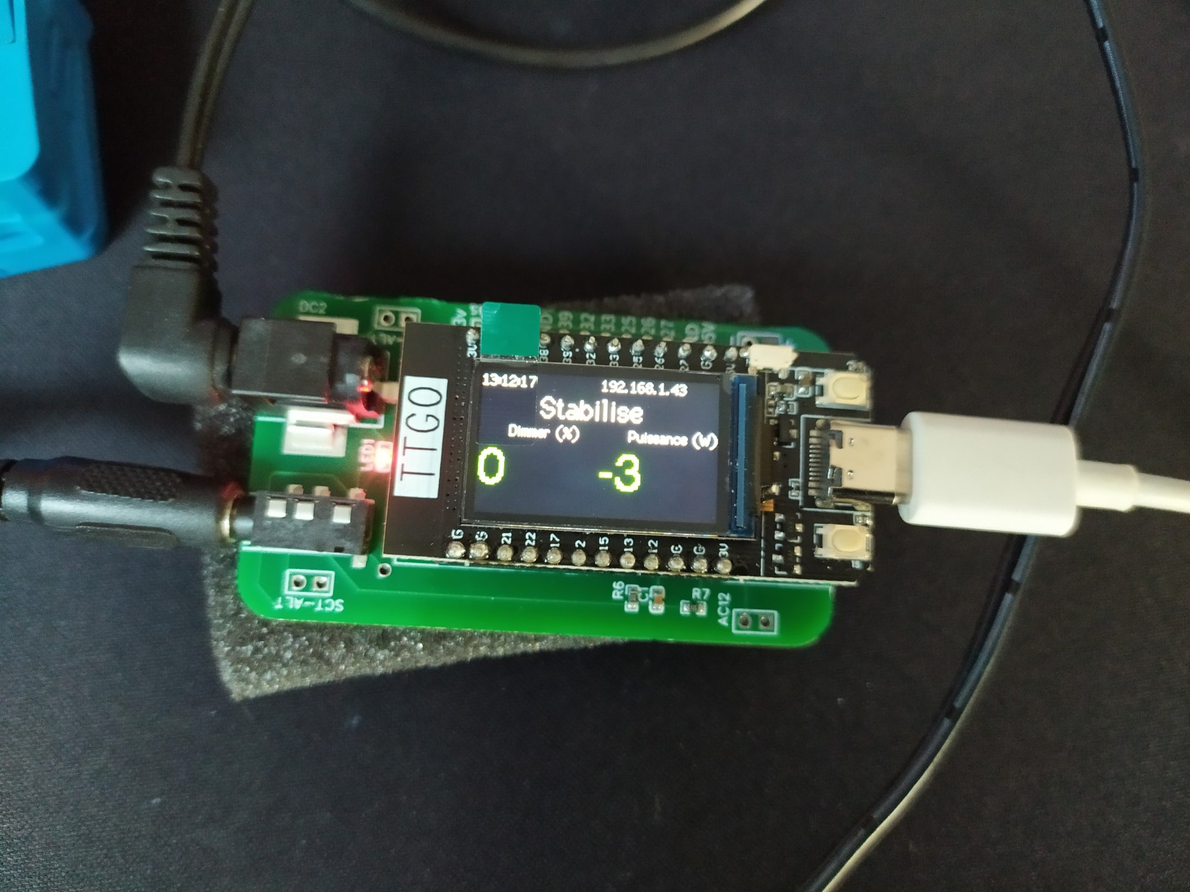
to then be integrated into a table or other after uploading
[](https://pvrouteur.apper-solaire.org/uploads/images/gallery/2022-03/image-1648140411579.jpg)
Preparing the 12V-AC power supply
You have to open the power supply and remove the diode bridge present inside.
[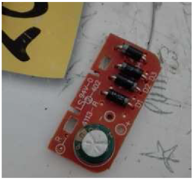](https://pvrouteur.apper-solaire.org/uploads/images/gallery/2022-03/image-1648140564635.png)
then resolder the coil outputs to the 12V power cable
[](https://pvrouteur.apper-solaire.org/uploads/images/gallery/2022-03/image-1648140538306.png)
Your 9-12V power supply is now ready.
It is advisable to check before the AC voltage delivered by the power supply.
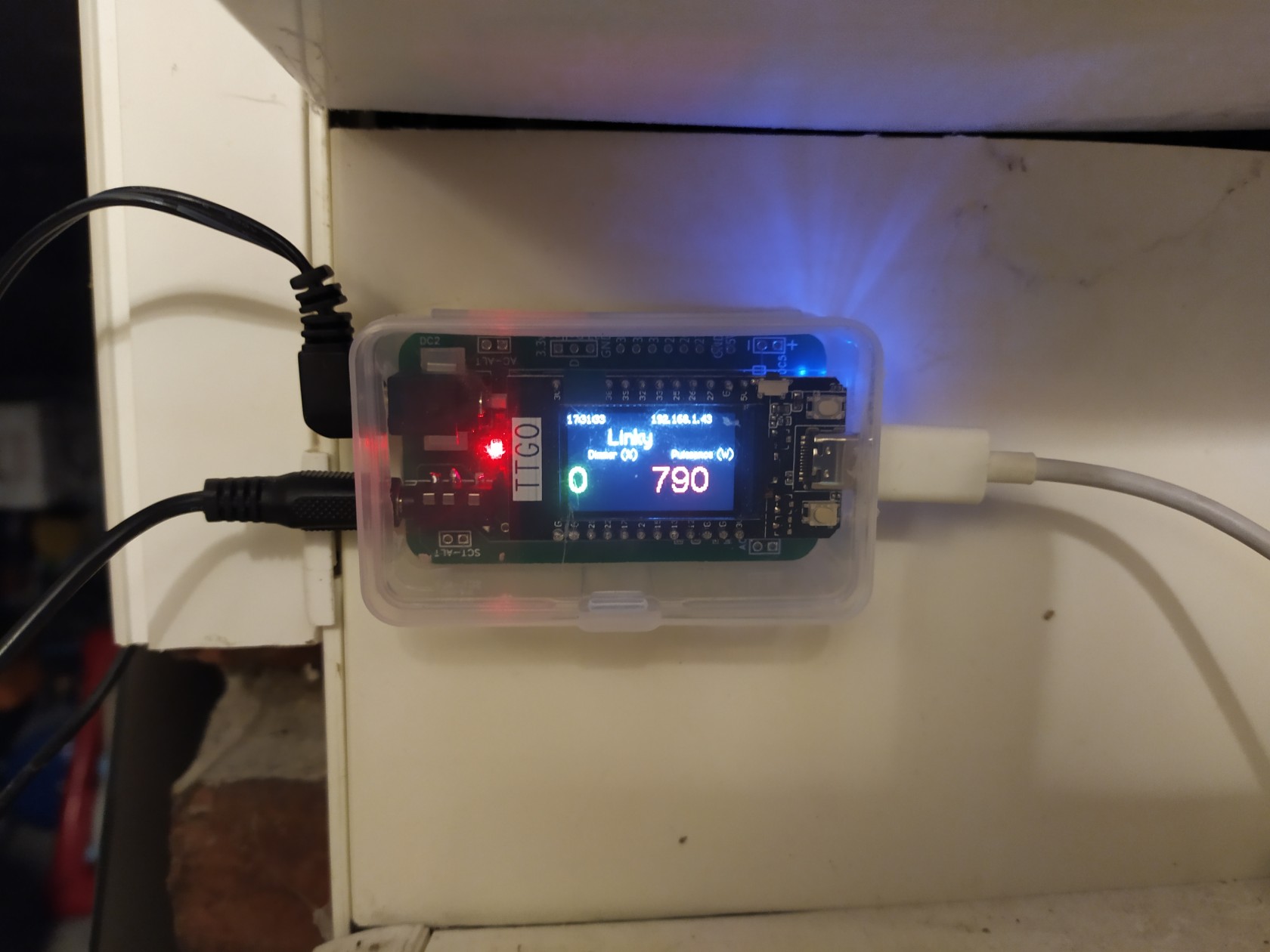
##### Upload
Once the assembly is mounted, you can upload the firmware as[ indicated in this post](https://pvrouteur.apper-solaire.org/books/pvr-installation-du-code/page/pvr-televersement-du-code-en-usb)
you will in principle have a functional Pv router
[](https://pvrouteur.apper-solaire.org/uploads/images/gallery/2022-03/image-1648140815878.jpg)
# 11 - Operation and use of the router
### Generality
The Photovoltaic Router is in charge of analyzing the direction of the current at the level of the electric meter thanks to the probe placed on the Phase wire.
If the current is positive, the house consumes current from the electrical network.
If the current is negative, the solar panels present provide more energy than what the house currently consumes.
The purpose of the Pv router is therefore to increase the power of a remote load to compensate for this overproduction.
In general, this load is an energy or heat storage area that will be needed at a later time (Hot water, mass heating, battery, EV, etc.)
The self-consumption of your photovoltaic installation is therefore maximized, and its impact on the electrical network is reduced. (and associated costs)
### Detail of the Web part.
Once the code has been uploaded (firmware and filesystem) and the entire router has been installed, it is possible to connect with your Web browser to the IP that is displayed on your PV router display.
You can therefore consult the information sent by the PV router.
[](https://pvrouteur.apper-solaire.org/uploads/images/gallery/2022-03/image-1648219178959.png)
On this interface you will find a gauge with the power requested from the network and the power requested from the dimmers (in %)
For the power requested from the network, there are **3 states that can be configured:**
\- **Stable**: the PV router has stabilized consumption.
\- **Injection**: The Pv router will gradually increase the load to stabilize consumption
\- **Grid**: The Pv router will reduce the load to limit the needs of the house.
On this interface, there is also an ON/OFF Oled button which is in charge of turning the Oled screen on or off.
it can just be a delay on or off until the next button press.
(ON/OFF or timer)
This button is also remote on the PV router, it is the right button of the TTGO
[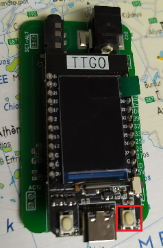](https://pvrouteur.apper-solaire.org/uploads/images/gallery/2022-03/image-1648219622636.png)
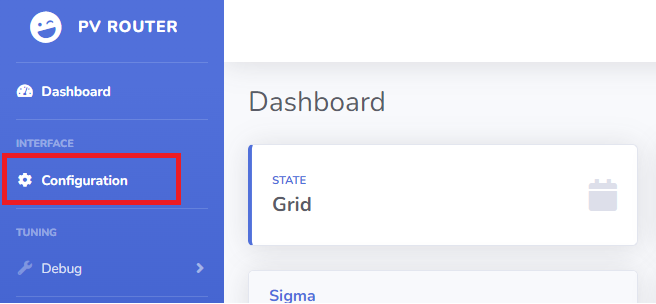
### Configuring the web part.
on the base page, there is a "configuration" link that points to the /setup.html page
### [](https://pvrouteur.apper-solaire.org/uploads/images/gallery/2022-03/image-1648219745425.png)
this page allows you to configure all the functions of the router.
[](https://pvrouteur.apper-solaire.org/uploads/images/gallery/2022-03/image-1648219762481.png)
#####
### MQTT: (Optional)
**MQTT Server**: IP of the MQTT server which collects information from the router (mainly for logs)
**MQTT Publish**: Indicates the location of the publication (Jeedom and Domoticz compatible data)
**IDX POWER and IDX DIMMER**: are the IDs configured on your home automation servers.
### DIMMER:
**Dimmer IP**: Is the IP of your 1st Dimmer which will receive the command from the PV router
**Consumption Limit (Delta)**: Is the value of the power from which the PV router will reduce the power of the dimmer
**Injection limit (deltaneg)**: Is the value of the power from which the PV router will increase the load of the dimmer
Connected load/W: Is the estimated power connected to the 1st dimmer, this value in W facilitates regulation.
**Limiter in %**: Is the 1st security to avoid asking too much power from your dimmers.
the value is defined by the sum of all the dimmers that are associated with your PV router
For example where your 1st router is limited to 80% power and the 2nd is limited to 40%.
the sum of the 2: "120" is therefore entered in the **Limiter box.**
###
Functional configuration
**If the SCT013 probe is connected upside down and therefore sends a negative** value instead of positive, the "polarity" button must be unchecked
The COSPHI represents the offset between the sync carrier and the network, this value is by default at **5**
It is not advisable to touch it.
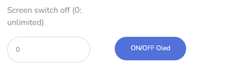
To preserve the life of the display, it can be switched on on demand
[](https://pvrouteur.apper-solaire.org/uploads/images/gallery/2022-03/image-1648220626300.png)
la valeur 0 indique que l'afficheur est en mode ON/OFF
une autre valeur représente le nombre de seconde avant son extinction
le bouton "application des paramètres" applique les valeurs provisoires au routeur
WARNING: these values are not final and stored in memory. they are there only to test the validity of the configuration, and will be reset at the next reboot To definitively apply your configuration, you must validate it using the button
[](https://pvrouteur.apper-solaire.org/uploads/images/gallery/2022-03/image-1648220787774.png)
### Special feature of AP mode (access point)
By default, if the wifi file is not configured, the router goes into AP mode, it will create its own wifi network.
the Wifi network will be of the PV-ROUTER-XXXX type.
The password will be PV-ROUTER
the IP address of the PV router will be 192.168.4.1
if a dimmer has been configured to connect to this network, the PV router will automatically detect it, and route the photovoltaic surplus to this dimmer.
For reasons of use, it is currently only possible to put 1 single dimmer on the network in AP mode.
# 50 - History of updates
**Update of 03/09/2022**
\- Integration of AP mode by défault with personalised SSID
**Update of 06/08/2022**
\- Access point (AP) mode for site without Wifi, automatic configuration when dimmer is connecting
**Update of 05/24/2022**
\- Compatibility with frontius et envoy S et R
**Update of 03/24/2022**
\- Wifi reconnection in case of network loss
**Update of 03/03/2022**
\- Addition of the temperature of the 1st dimmer on the TTGO display
**Update of 02/26/2022**
\- Added screen sleep feature (requires filesystem update)
**Update of 01/02/2022**
\- Fixed sending data to Jeedom via MQTT
**Update of 01/17/2022**
\- Translation into English of display information
**Update of 01/10/2022**
\- removal of the Emonlib library.
**Update of 17/12/2021**
\- Printing of the V2 card for TTGO mounted in SMD and compatible with the TTGO box
[](https://pvrouteur.apper-solaire.org/uploads/images/gallery/2022-03/image-1648138865148.png)
**Update of 15/11/2021**
\- Printing of the V1 board for TTGO mounted in SMD
[](https://pvrouteur.apper-solaire.org/uploads/images/gallery/2022-03/image-1648138817928.png)
**Update of 10/10/2021**
\- TTGO-Tdisplay support
**Update of 07/10/2021**
\- Passage of the filesystem in LittleFS
**Update of 05/15/2021**
\- Fixed IDX and display bug
**Update of 04/28/2021**
\- Correction of the library provided by Robotdyn
**Update of 04/16/2021**
\- Init Commit for ESP32
**Update of 05/18/2019**
\- Fixed IDX and display bug
**Update of 31/12/2019**
\- Implementation of the configuration page
**Update of 26/12/2019**
\- OLED display fix
**Update of 07/09/2019**
\- Documents
**Update of 07/18/2019**
\- V3 map printing for lolin or Wemos
[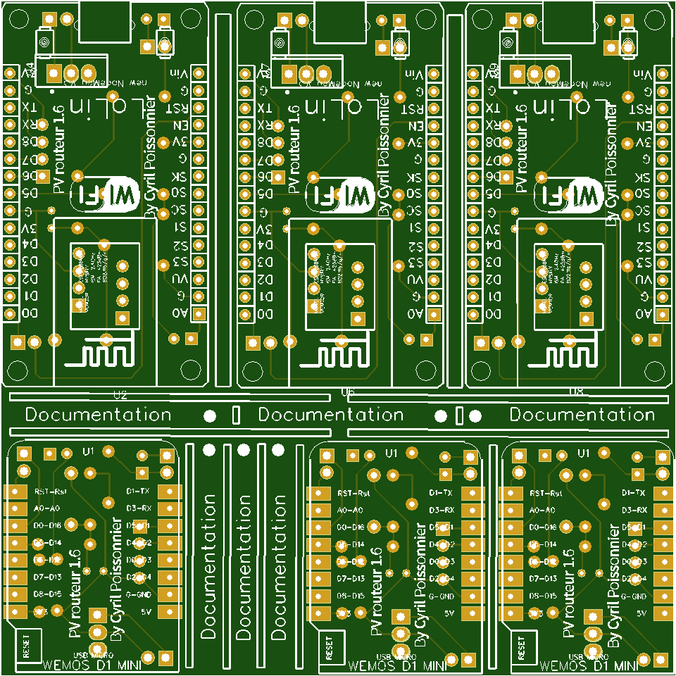](https://pvrouteur.apper-solaire.org/uploads/images/gallery/2022-03/image-1648138727532.png)
**Update of 07/07/2019**
\- Support for Domoticz
**Update of 20/06/2019**
\- Init Commit for ESP8266
**Update of 05/28/2019**
\- Printing of the V2 map
[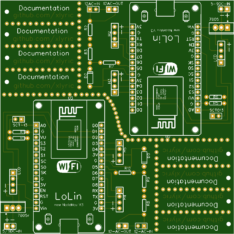](https://pvrouteur.apper-solaire.org/uploads/images/gallery/2022-03/image-1648138520166.png)
**Update of 12/05/2019**
\- V1 card printing
[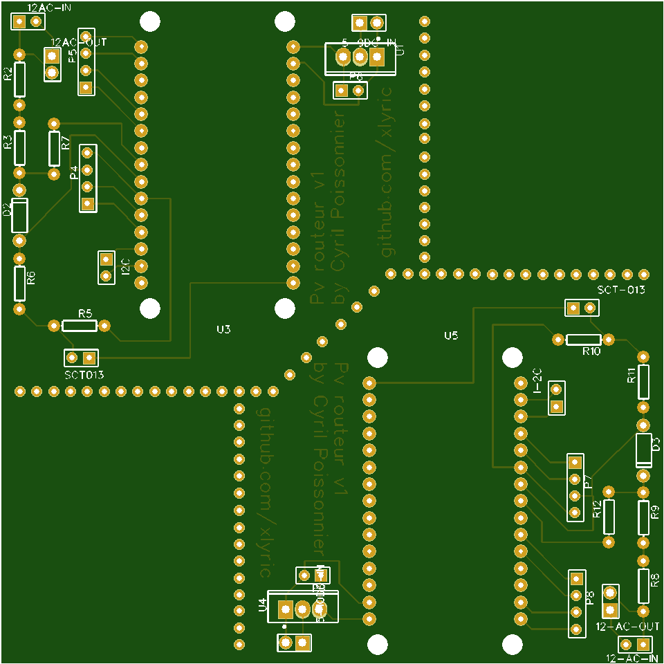](https://pvrouteur.apper-solaire.org/uploads/images/gallery/2022-03/image-1648138482208.png)
# Numeric dimmer
# 01 - Install of Visual Studio Code
To transfer the code to the microcontroller (ESP8266 or Robotdyn) it is necessary to install[ Visual Studio Code](https://code.visualstudio.com/).
Once installed, you must install the [PlatformIO](https://platformio.org/install/ide?install=vscode) package which will be used later for all your projects and not only for the Dimmer or the Pv router.

# 02 - Copy or update repository sources
The sources are available on the Github (a code repository web server)
once your Visual Studio is launched, go to your Terminal and type
```shell
git clone https://github.com/xlyric/PV-discharge-Dimmer-AC-Dimmer-KIT-Robotdyn.git
```
it will then clone the repository on your machine and you can adapt the code to your needs and upload it.
```shell
PS C:\Users\c_lyr\Documents\PlatformIO\Projects\1> git clone https://github.com/xlyric/PV-discharge-Dimmer-AC-Dimmer-KIT-Robotdyn.git
Cloning into 'PV-discharge-Dimmer-AC-Dimmer-KIT-Robotdyn'...
remote: Enumerating objects: 179, done.
remote: Counting objects: 100% (179/179), done.
remote: Compressing objects: 100% (136/136), done.
Recote: Total 179 (delta 90), reused 119 (delta 38), pack-reused 0 eceiving objects: 75% (135/179)
Receiving objects: 100% (179/179), 630.36 KiB | 2.58 MiB/s, done.
Resolving deltas: 100% (90/90), done.
```
you can then go to the directory created during the command
```shell
Resolving deltas: 100% (90/90), done.
PS C:\Users\c_lyr\Documents\PlatformIO\Projects\1> ls
Directory: C:\Users\c_lyr\Documents\PlatformIO\Projects\1
Mode LastWriteTime Length Name
---- ------------- ------ ----
d---- 10/03/2022 16:53 pv-router-esp32
```
In the case of an update, you can update your code again with the following command
```shell
git pull
```
[](https://pvrouteur.apper-solaire.org/uploads/images/gallery/2022-03/image-1648136329142.png)
#### Default configuration
There is nothing more to configure in the dimmer,
you just have to upload the corresponding version to the dimmer.
Wifi configuration is done in Wifi autoconnect.
He creates a WiFi "dimmer" with a web interface accessible at 192.168.4.1 which allows you to configure your personal WiFi.
# 03 - USB code upload
Uploading is done with Visual Studio Code (VS) using the PlatformIO tab
[](https://pvrouteur.apper-solaire.org/uploads/images/gallery/2022-03/image-1648136519736.png)
During your 1st Upload, you must plug in your ESP, wemos or TTL/USB adapter for programming
There are different versions available depending on what you are using as a dimmer.
[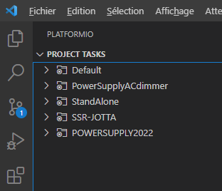](https://pvrouteur.apper-solaire.org/uploads/images/gallery/2022-05/image-1651775770647.png)
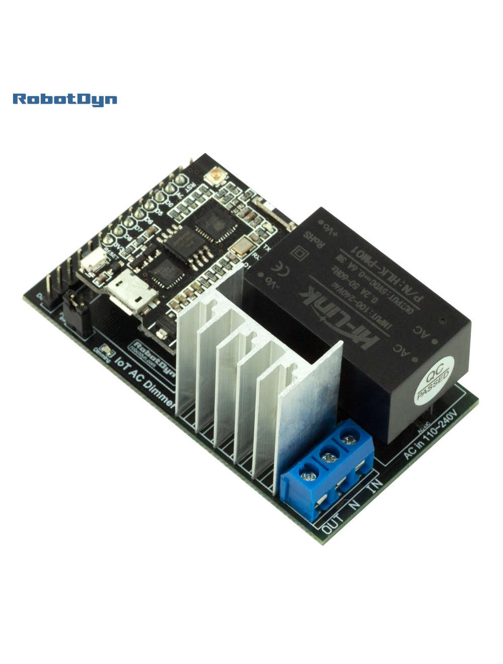
1. **PowerSupplyACdimmer** is used for old version of Robotdyn dimmer,
this is the easiest version to install, it was compatible with the daughterboards supplied with the PV router V1.2 TTGO
the recommended maximum power is 5A (and not 8A as indicated by the manufacturer)
( D0 and D1(zc) are used )
the Dallas probe uses D2
[](https://pvrouteur.apper-solaire.org/uploads/images/gallery/2022-05/image-1651775952029.png)
2.
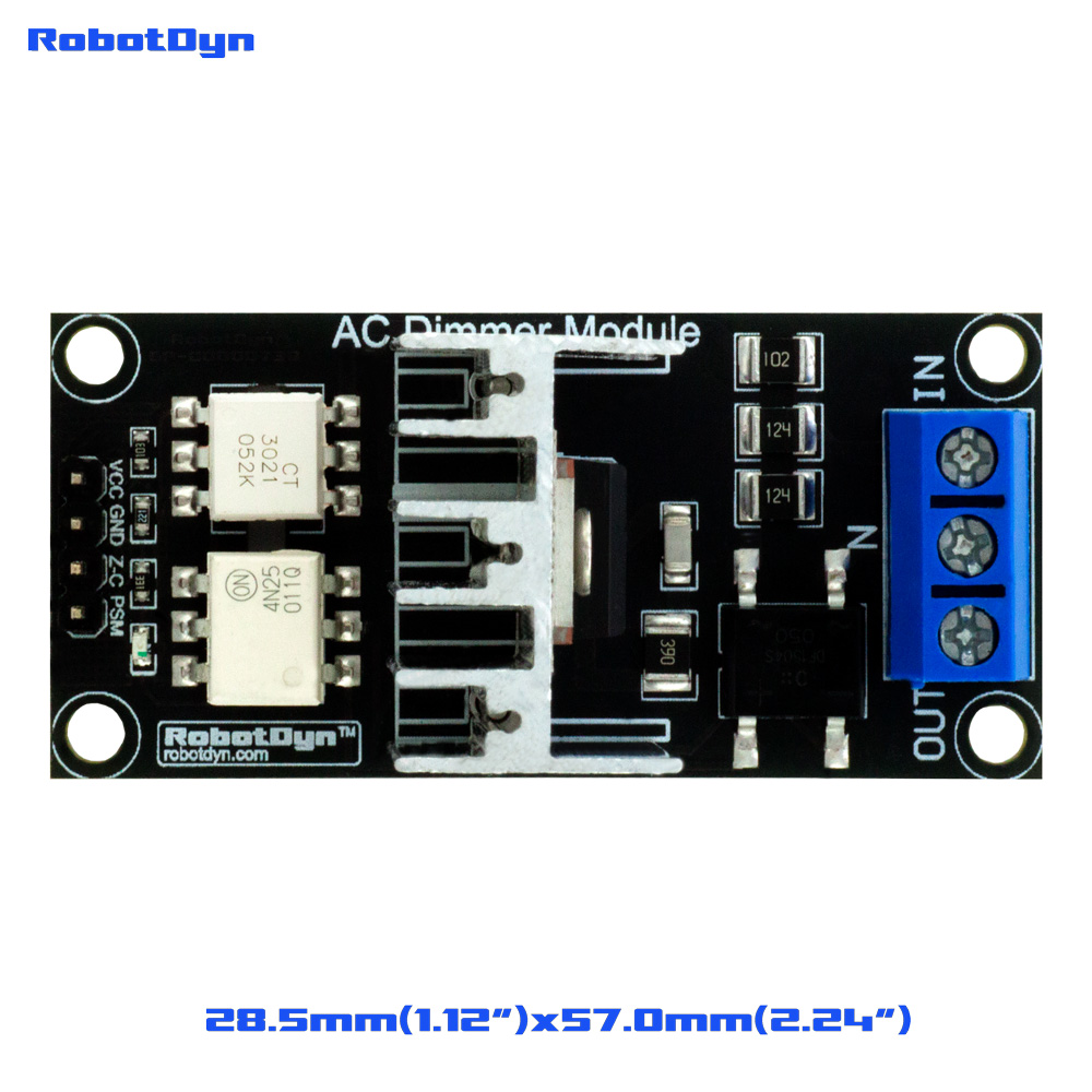
**StandAlone** is used to later add a Robotdyn dimmer to your ESP.
there are different versions supporting more or less power,
on the smallest pod, the maximum recommended power is 5A (and not 8A as indicated by the manufacturer)
on the 16A model, I think you should not exceed 12A -> ~2500W (to be tested)
( D5 and D6(zc) are used )
The Dallas probe uses D7
[](https://pvrouteur.apper-solaire.org/uploads/images/gallery/2022-05/image-1651775990428.png)
3.
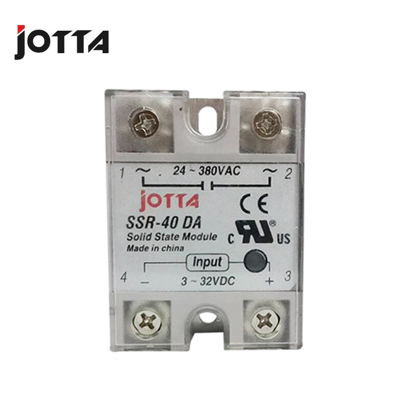
SSR-JOTTA is used to live control an SSR The - connects to the GND and D4 to the + of the Jotta
The Dallas probe uses D2
[](https://pvrouteur.apper-solaire.org/uploads/images/gallery/2022-05/image-1651776015419.png)
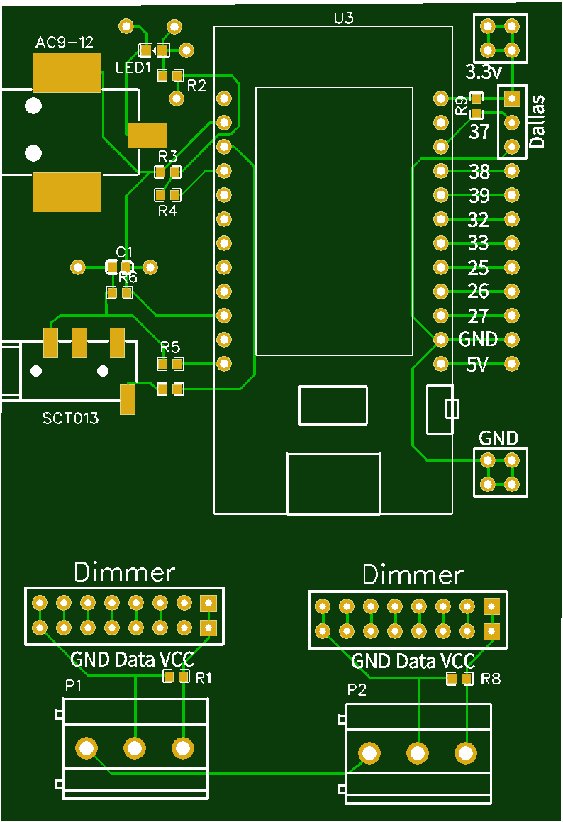
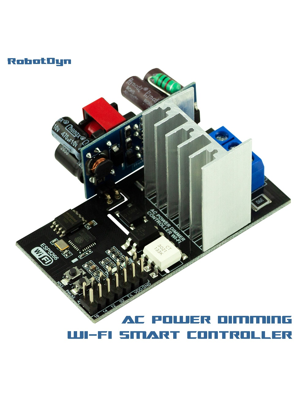
4. **POWERSUPPLY2022** is for the 2022 version of the Robotdyn dimmer.
it requires a TTL adapter for the 1st programming.
the jumper between vdd and 3.3V must be removed during TTL programming
then put back when connecting the assembly to the 220V
The Dallas probe uses pin 14 - GND at 16 and 3.3v at 12
[](https://pvrouteur.apper-solaire.org/uploads/images/gallery/2022-05/image-1651776030344.png)